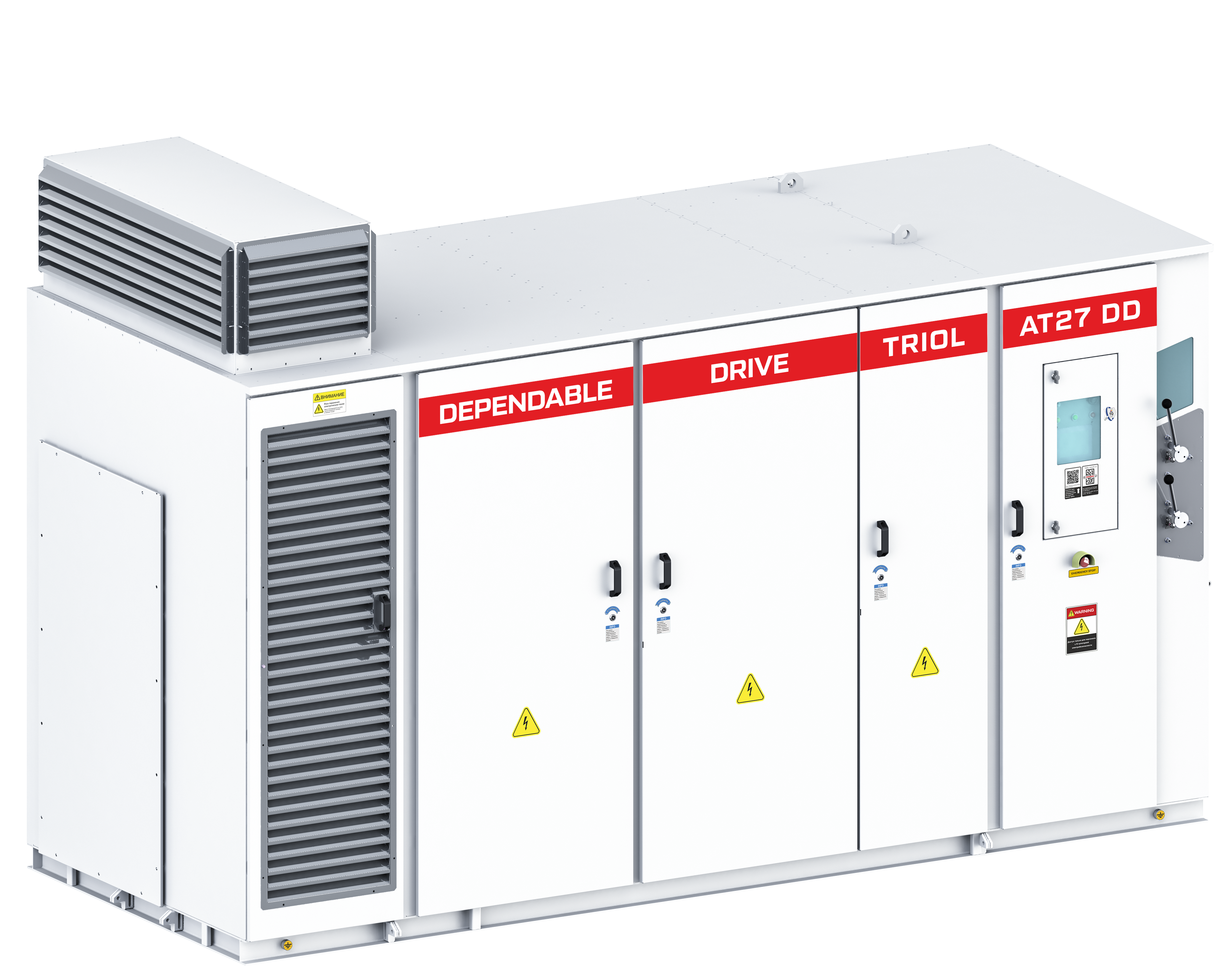
Triol AT27 line Dependable Drive
Place an order
Distinctive benefits
+1°C ... +50°C
Operating temperature maximum range
NEMA3R (IP54)
Enclosure
7”
Color touchpad
≥ 0.96
High power factor
Induction, synchronous, and PMM
Wi-Fi Wizard
Output voltage and current sinusoidal
Output voltage and current sinusoidal
About product
The AT27 VFD DD model
is a precisely engineered, versatile and reliable solution for outdoor use in humid and/or dusty industrial locations without conductive dust, tropical and equatorial climates, in weak power mains applications and with power supplied from diesel power plants of comparable power level. This unit is indispensable in projects that cannot use generalized industrial equipment due to an unsuitable enclosure IP rating. Built-in input disconnector with a grounding switch ensures the enclosure is safe for maintenance personnel. Input surge arresters guarantee performance sustainability in incidences of lighting and main over-voltage. Minimal mounting expenses, only input and output power cables are required.
Features include:
Welded frame, Door seal, Cooling fans and power components are located in a separate compartment, Anti-condensation heating, Labyrinth air passage for ambient air, Air filters for dust and moisture mitigation, Transports easily in a standard size shipping container
Triol AT27 VFD DD Design and Construction
The AT27 VFD DD is a single-cabinet, welded frame design that consists of several compartments: Transformer compartment, Power cell compartment, Control compartment, Switching compartment, Air filter chamber, Fans The switching compartment includes the input disconnector and grounding switch, surge arresters, and power terminals. Additionally, this compartment can be equipped with a vacuum contactor and a transformer to supply auxiliary power. The switching compartment door is extra wide, for convenient maintenance.
Triol AT27 VFD DD Cooling System
This model uses a forced air-type cooling system. Exhaust fans are located on the unit's roof and can be removed for transport. The air filter chamber has a labyrinth air passage for ambient air, and the air filters reduce intrusion of dust and moisture.
Specifications
|
Input |
||
| Input voltage, kV |
3; 3.3; 4.16; 6; 6.3; 6.6; 10; 11 (-15 % ...+10 %) -45% continuous with power limit -100% not less than 100 ms with controlled generator mode of the motor |
|
| Input frequency, Hz | 50 / 60 (-10 %...+10 %) | |
| Power, kW |
3.3 kV 4.16 kV 6 / 6.6 kV 10 / 11 kV |
from 160 kW up to 3000 kW from 160 kW up to 3500 kW from 200 kW up to 4000 kW from 320 kW up to 4000 kW |
| Power factor | 0.96 | |
| THDi (input current), % | < 5 | |
| Pulses of rectifier |
18; 24; 30; 36; 48; 54; 60 (depends on the number of cells in each phase) |
|
| Overvoltage protection | Surge arresters | |
|
Output |
||
| Rated output voltage, kV | 3.3; 4.16, 6; 6.6; 10; 11 | |
| Output frequency, Hz | from 0.5 up to 120 | |
| Frequency resolution, Hz | 0.01 | |
| Output current, A | 21…600 | |
| Overcurrent characteristics |
120 % of rated value for 120 sec 150 % of rated value for 3 sec |
|
| THDi (output current), % | < 2 | |
| THDu (output voltage), % | < 5 | |
| dV/dt value | < 1000 V/μs | |
| Efficiency, % | ≥ 97 | |
Options
| Options |
Description |
| Copper transformer
|
Copper bus bars are used to protect the transformer windings. The transformer performance parameters and efficiency are nearly identical to transformers with aluminum bus bars.
|
| Power cell bypass
|
Vacuum chamber design allows a power cell bypass, with a response time of not more than 4ms
|
| Additional power cell
per phase |
This reliability enhancement ensures continued nominal operation if voltage drops in the output sine filter, long cable line, or reactors (if available).
|
| Redundant cooling fans
|
Additional cooling fans feature a check valve system, to ensure uninterrupted operation in the event of main cooling fan failure.
|
| Additional PCB coverage
|
Circuit boards have a protective coating to eliminate corrosion due to aggressive air impurities.
|
| Electromagnetic door lock
|
Power compartment doors are protected from opening when motor is operating.
|
| Auxiliary voltage ~3x480 V
|
Supplies control system with 480 V AC power.
|
| Built-in transformer for auxiliary supply
|
No external auxiliary voltage supply necessary. A built-in transformer with input fuses provides power from medium-voltage mains. This option includes input vacuum contactor 10 kV, 630 A.
|


 Google
